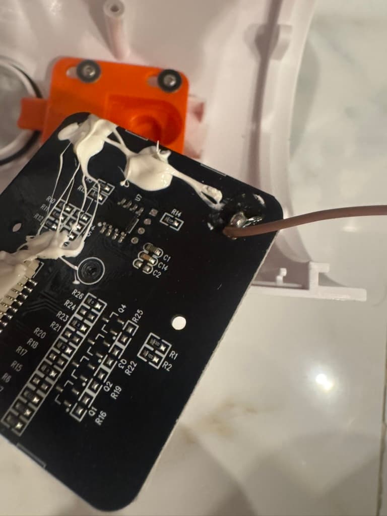
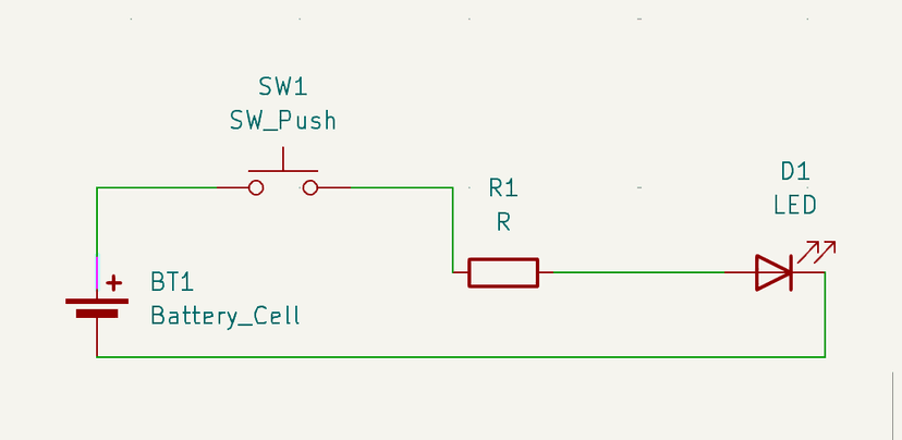
@aryan0building a battlebot (12V, <3kg) for a school competition :D
Completed wiring and circuit, need to work on frame now
@Siwen0Continued work on the 4 port usb, routed all the connections up. I've decided to put a large hole at the top left for a keychain and multiple smaller holes for a mounting a 3d printed case I'll be designing later. I'm debating on if I should expose some of the pcb so I can put Silk screen art on it or lasercut a piece of plexiglass for the case. I also want to get everything on a breadboard so I can test if it actually works. I found out you can get breakout components for smd components and usb ports so I'm definitely going to buy some. :pcb:
@Siwen0Today I researched info about USB-C for PCB design so with the end goal of a USB-C 4 Port Hub and started working on a 4 port version of the USB hub I was working on.
@Siwen0Today I did: the PCB Hacker Card jam and USB Hub jam
@RyanDiLorenzo-U04JGJN2B400I completed my first full PCB assembly using a PCB I made. The PCB I created it a re-creation of the stock one used for my 3D Printer that I added some new ports/connectors for, all without the original PCB files. I used both leaded solder and bismuth solder paste, this was my first time using solder paste and first time working with bismuth, I found bismuth's melting point to be excruciatingly low since the 4-layer PCB had so much thermal mass. Here are some photos I took along the way, lmk if anyone has questions.
@Amber0wow, been a while since I’ve scrapbooked, I should really get back into this!
Today I finished the schematic and PCB for my #C07LESGH0B0| submission! This is my first time doing anything like this and it was pretty fun! Tomorrow I'll be working on the case and, if I finish that, the firmware!
@YeGao0Been learning more about PCB desgin as I'm kinda of interested in soldering my bin parts onto a custom PCB
@TheScientist1010I forgot that I have to scrapbook for #C07NUNPGEU8|, so I thought I might make one now. While designing my #C07LESGH0B0|, I’m kind of stuck, I had everything routed, but I want to add more components, so I unrouted everything. I never thought I’d be able to design a PCB before, but I’m making progress. I figured out how to add a display, and all the switches, but my main problem now is that I don’t know how to make the keys RGB, and I am running out of GPIO pins. I’ve heard of something called an IO expander, which could fix my GPIO pin problem, but I still don’t know about the RGB. Also, I am currently at an FRC competition, so I will probably finish coding auton for that soon. I’ve done all this #C07LESGH0B0| yesterday and today, for a total of 6 or 7 hours so far just on this project, and 2 hours of (tracked) FRC work; I wasn’t tracking my FRC work earlier. I will update y’all on this and FRC soon!
On a side note, I got my friend to try #C07LESGH0B0|!
@YeGao0Tried to make a simple temperature pcb thingy
@YeGao0Finished the wiring and the outline, I might add more ports, I wonder if it possible to make it face up? Unfortunately I don't think there a cable at least in the PCB design phase
@GregorDavies-U04FX4ZMBJ90I shipped a opensource motor controller and datalogging system for Greenpower race cars, designed in order to maximise the speed and reduce the cost of these vechiles designed by young engineers and university teams. The motor controller is based around the RPI pico w and is a simple THT based pcb easy for teenagers to assemble and fix when at races, it's currently being made by jlcpcb thanks to onboard and I should be able to fit it to the car next week. Picture of me and my friends car jaws included which has been 13 years of work in the making. github.com/Gregor-Davies/Zevallos
@LinuxDino0PCB card part 2: (WIP). I am currently learning PCB design (for OnBoard). First, I followed the tutorial and learnt some basic stuff like how to use the CAD editor and search components, etc. Then I just decided to straight-up build a whole computer in the chip, which is actually a secret radio / tranceiver thing. This will be my final scrapbook. GitHub link: github.com/LinuxDinoGitHub/DinoCard
@AdityaPV0Introducing PCBs for Blot!!
You can experiment with printed electronics with a conductive ink pen and your blot with this.
Here is my implementation of my PCB with Blot.
(This project was done before the separate repo suggestion. Hence the file and the commits are in a common repo)
I have also attached some sessions of collatz conjecture project, since it doesn't deserve a separate post, and it was the starting point for this project.
github.com/Vipremigini/Myfiles/blob/main/pcb.js
@Anson-U07FPDRVCD80ArduinoFlightController
Flight controller based on the Atmega328p microcontroller
The gerber files can be found in my github repository: github.com/YeetTheAnson/ArduinoFlightController
Features
• Supports MultiwiiConf flight controller software
• Has FTDI pins for programming
• Has 3-axis accelerometer and gyrometer
• Barometer to measure altitude
• Has 3-axis compass
Attached below are some images of the PCB, and a video of the 3d view
@anne0tried to make a hardware TOTPkey and failed miserably because (1) the routing was crazy difficult since im not good at PCB stuff and (2) the firmware part legitimately made me cry. find it at github.com/arsoninstigator/hardware-TOTkey
@tyzrichard0Over the last few months, I took part in a competition (Steamunity: Design for Humanity) and created a cool circuit to improve two-way communication between elderly residents and their visitors! It builds on the doorbell system to help alert elderlies that suffer from hearing disabilities. Check out the repo: github.com/DakshRocks21/Steamunity
Can't post this without acknowledging my fellow no-lifer @dak5h who has been a blast to work with throughout, huge credits to him for making this with me.
And below is a picture of the stuff in action. It's just circuits for now, but our team's gonna 3D model some cool stuff to make the entire setup look good.
@HarshavardhanTammina0REPOST as all sessions weren't included previously
#C06SBHMQU8G| i've reached a milestone with my DAW Controller project. i have completed the wiring/circuit design and schematic using the Fritzing software. the next milestone to achieve is wiring it physically.
you can view the github repo here: github.com/hrtacp/DAW-Controller/tree/wiring
@Anson-U07FPDRVCD80USB3Hub
Custom made USB 3 hub using USB5534B Host Controller
Gerber files can be found in my github repository: github.com/YeetTheAnson/USB3Hub
Features
• Supports 5Gbps SuperSpeed protocol (With supported hardware, and while using one usb port only)
• Has 4 Usb 3.0 capable ports (480Mbps when used simultaneously)
• Type C input
Parts (Significant)
• USB5534B-5000JZX USB Host Controller
• Type C input
• 4x USB3.0 output
Attached below are some images of the PCB, and a video of the 3d view
@Mirrreeek0uTesla · A small but impressive musical Tesla coil.
Well.. it's not very impressive at the moment, I can't quite fit the deadline (spent multiple days just trying to flash the ATmega328P with a bootloader - couldn't get it to work). Most of it is soldered up but I bought a few parts in the wrong package so couldn't finish it and try it out (not like it would work without spending a week more on it anyways). I'd really love to get this to work but also am kinda getting tired of it, so it might take some time. More at the GitHub repo.
I've never worked with ATmegas before (I mean like making a PCB for it, I've obviously used Arduinos), and for some reason thought it works kinda like an ESP32 - everything is flashed over UART. Well it's not. It first needs a bootloader which is flashed over SPI and of course I haven't added a header for the SPI pins. Had to get creative.
Also I dropped the secondary while the epoxy was drying so it's covered in stuff and looks ugly:( I'll probably rewind a new one, it's small so it's not that much work.
GitHub: github.com/Mirrrek/uTesla
@ShreyasJain0Post 28
🏎️ RaceCraft: An engaging simulation tool that allows users to create and simulate races with custom teams, drivers, and circuits. By leveraging dynamic race simulation and interactive visualizations, RaceCraft offers an immersive experience for motorsport enthusiasts and data lovers alike.
Features
• Race Simulation: Simulate races by selecting drivers, circuits, and starting lineups. View simulated results with positions and points.
• Leaderboard: Display a sorted leaderboard showing driver positions and points based on race results.
• Timelapse Visualization: Watch a timelapse of drivers' positions on the circuit throughout the race.
• Dynamic Updates: Experience real-time race updates with random elements like crashes and upsets to enhance the excitement.
• Responsive Design: Fully functional and visually appealing across all devices and screen sizes.
Note: RaceCraft is not yet currently complete. Some features may be broken or imperfect. Currently working features include:
• Driver selection
• Circuit selection
• Team selection
• Race simulation
• Leaderboard display
Try it out @ race-craft.vercel.app
Open source @ github.com/shrysjain/racecraft
@anne0i built (/ am building) a micropad ! while this would be much simpler if i was working with arduino, i started this project with esp32 on wokwi as a part of the #C06R2QQT5M4| electronics project. unfortunately, while working with that microcontroller, it was announced that it was to be removed from the bin form since it was too expensive. i was forced to switch over to pi pico to salvage some of my work so here we are ! i'm designing the pcb so i can have it fabricated so i can work with an arduino (that i'll source myself) and make an actual funky macropad with latest functionalities. find my repo at github.com/arsoninstigator/macropad.pi-pico
@Briyan0Made some bin projects for #C056AMWSFKJ|!! My fav one is my flippedy floppedy circuit which involves a shift register for the controlling of 8 leds for different blinking patterns!
@Mudasir0I designed a USB hub in EasyEDA for onboard. I started with something like this tutorial, although i had to find my own parts which were slightly different, due to unavailability: jams.hackclub.com/batch/usb-hub/part-2. This let me get two usb-a female ports leading into 1 usb-a male connector, and then I modified it by adding another usb-c (female) port.
The schematic and pcb files are all on github here: github.com/mud-ali/usb-hub
@LinuxDino0PCB card: (WIP and probably won't finish by the end of arcade since school is starting). I am currently learning PCB design (for OnBoard). First, I followed the tutorial and learnt some basic stuff like how to use the CAD editor and search components, etc. Then I just decided to straight-up build a whole computer in the chip, which is actually a secret radio / tranceiver thingy. This might be extremely difficult, but so far I have found the modules needed to build this thing. I am just worried about the final thing not working so I am making this a checkpoint. Demos attactched. GitHub link: github.com/LinuxDinoGitHub/DinoCard